Sonifex RB-IPE - IP Extender for GPIO & Analogue Control Signals
Sonifex RB-IPE
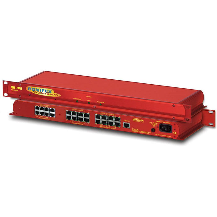
The Sonifex RB-IPE is a 1U rackmount unit designed to provide remote control of GPIO and analogue control voltages over an Ethernet network. Configured using a built-in web server, two units can control each other across an Ethernet network, or a single unit can be controlled via Ethernet commands and the web server interface. The unit can be used in any position where you need to remotely acquire GPO signals or remotely control equipment, for example controlling equipment at unmanned posts, outstations or transmitter sites.
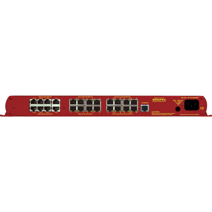
Each unit has 16 x general purpose inputs on 8 x RJ45 connectors, consisting of 8 x isolated current sink inputs and 8 x pull to ground protected inputs; and 16 x general purpose outputs on 8 x RJ45 connectors using 8 x isolated relay change-over contacts and 8 x opto-isolated contacts. These rear panel RJ45 connectors have an LED for each GPIO which shows its state.
On another 8 x RJ45 connectors there are also 8 x 0 to 3.3V/5V/12V input signals and 8 output signals nominally at 0 to 3.3V output, with other output voltage configurations possible. The outputs can all be controlled from the inputs of another RB-IPE, or from Ethernet commands.
This allows any tallies and control signals, together with analogue potentiometer movements, to be sent across a network, e.g. for remote alarm points, to trigger failure alarms at a transmitter site and to control remote equipment.
When two units are connected together at different sites, if a general purpose input state changes at one site the unit sends the new state to the other site and the appropriate opto-isolator output changes on that unit. Similarly input voltage controls are monitored and the changing voltage is sent to the remote unit where an output voltage changes accordingly.
The signals can be routed and distributed such that a single input signal to a unit on one site can be routed to multiple outputs in a unit on another site and/or have the logic inverted and distributed to multiple outputs. Also, the state of the GPOs when the unit is powered on can be configured, allowing more reliable recovery of external connected equipment from a power-fail condition.
The analogue I/O control signals can be mapped to give different ranges between the incoming and outgoing signal, e.g. 0V to 5V input giving a 0V to 12V output, or a linear input mapped to a log scale output. Also, by programming threshold values, analogue input voltages can be mapped to GPO pins, e.g. for sending a signal to a GPO when a volume knob is turned too high.
The web server in the RB-IPE can be configured with a static IP address or by using DHCP.
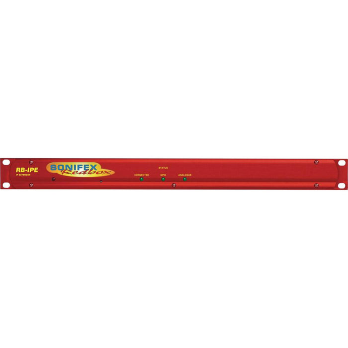
The three front panel green LEDs give an indication of Ethernet connectivity, i.e. they show when commands are being sent/received. The CONNECTED LED shows link status, the GPIO LED illuminates whenever a GPIO state changes and the ANALOGUE LED indicates a change in state of the analogue voltage signals.
The RB-IPE is powered from a universal mains input between 85-264V AC at 47-63Hz.
Sonifex RB-IPE Specifications
Rear Panel Connections
- Isolated GPI: 4 x RJ45 sockets, with LED status indicator per input
- Active Low GPI: 4 x RJ45 sockets, with LED status indicator per input
- Relay GPO: 4 x RJ45 sockets, with LED status indicator per output
- Isolated GPO: 4 x RJ45 sockets, with LED status indicator per output
- Analogue Control Inputs: 4 x RJ45 sockets
- Analogue Control Outputs: 4 x RJ45 sockets
- Ethernet Port: RJ45 with status LEDs
- Mains Input: Filtered IEC, continuously rated 85-264VAC @ 47-63Hz, 10W max
- Fuse Rating: Anti-surge fuse 1A 20 x 5mm
Input & Output Detail:
- General Purpose Inputs: 8 x isolated current sink inputs from Inputs: 3.3V to +24V (Max input range: 0V to +24V) 8 x pull to ground protected inputs (Max input range -24V to +24V)
- General Purpose Outputs:
- 8 x isolated relay change-over contacts: Nominal switching capacity (resistive load): 1A @ 30V DC (0.5A @ 125V AC)
- 8 x opto-isolated contacts: Maximum collector/emitter voltage
- peak: 35V DC @ 7mA
- Maximum collector/emitter current: 80mA @ 2.5V DC
- (Note: There is a 200 mA fused +5V power supply available on GPI ports 1 – 8 and GPO ports 9 – 16.)
- Analogue Control Inputs: 8 x 0V-3.3V, 5V or 12V input signals
- Analogue Control Outputs: 8 x output signals, nominally 0V-3.3V, 5V or 12V
Front Panel Indicators
- Power On: Red LED
- CONNECTED: Green link status LED
- GPIO: Green GPIO change status LED
- ANALOGUE: Green analogue control I/O change status LED
Physical Specification
- Dimensions:
- 48cm (W) x 10.8cm (D) x 4.2cm (H) (1U)
- 19” (W) x 4.3” (D) x 1.7” (H) (1U)
- Weight:
- Nett: 1.6kg Gross: 2.2kg
- Nett: 3.5lbs Gross: 4.8lbs